Getting Started
To start using Simple Procedural Walk you will need a Character with a Skeletal Mesh and its related Animation Blueprint.
Tip
Setting up procedural animations takes a little effort and constant tweaking until you are satisfied with the results. Hang in there, you've got this!
Set up the AnimBP
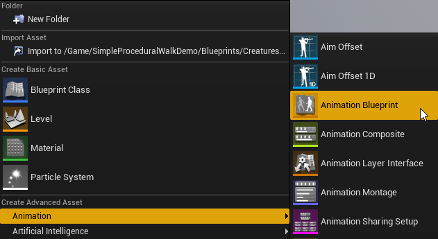
Right click on the Content Browser and click on animation > Animation Blueprint:
Rename it to your liking, for example AnimBP_Robot, and double-click to open it.
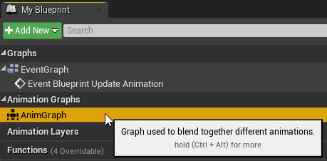
Open its AnimGraph by double clicking it in the My Blueprints section:
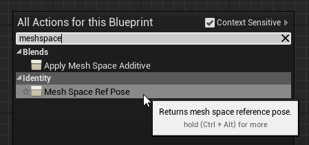
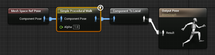
Start by adding a Mesh Space Ref Node by right clicking anywhere on the Graph and searching for it:
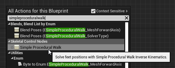
Then, add a Simple Procedural Walk Node:
Connect all nodes by dragging pins from one another to the Output Pose:
Configure the Node
With the Simple Procedural Walk Node selected (as shown in the previous picture), you will see its properties in a side panel on your right. Let's start configuring the utmost necessary ones.
Legs
Under the Skeletal Control Section, click on the + sign in the Legs property to add as many entries as there are legs.
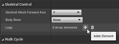
For this example, we are going to use the Dog Skeletal Mesh included in the downloadable example. Since the Dog has 4 legs, let's click on the + sign 4 times:
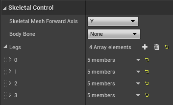
We are creating a number of Leg entries corresponding to the number of legs that our Skeletal Mesh has.
Note
The sequential auto-assigned ID numbers displayed on every entry of the array (in the image above, the numbers from 0 to 3) are what will be referred to as Leg Indices in this documentation.
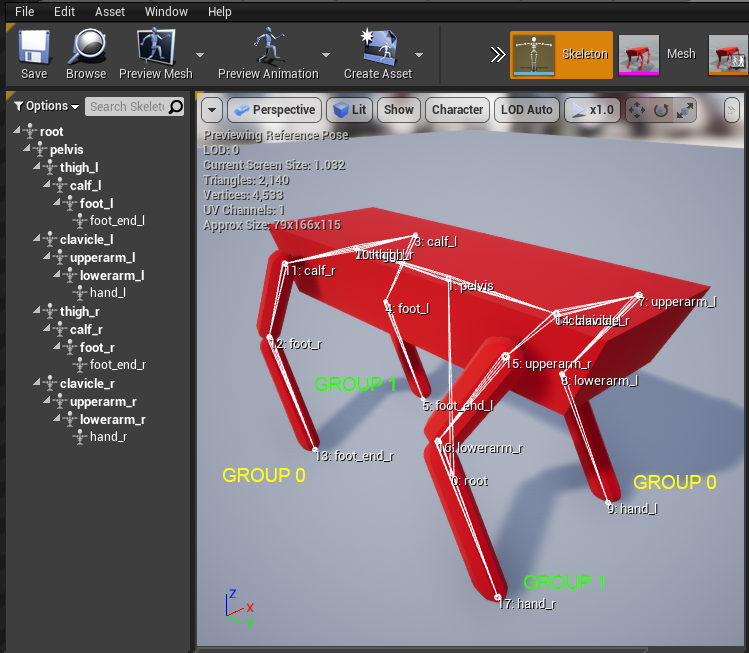
Before proceeding, we need to know which bones compose the legs of our creature. Open up your Skeletal Mesh, click on the Skeleton tab of your Top Right navigation bar and search for the beginning and ending bones of every leg:
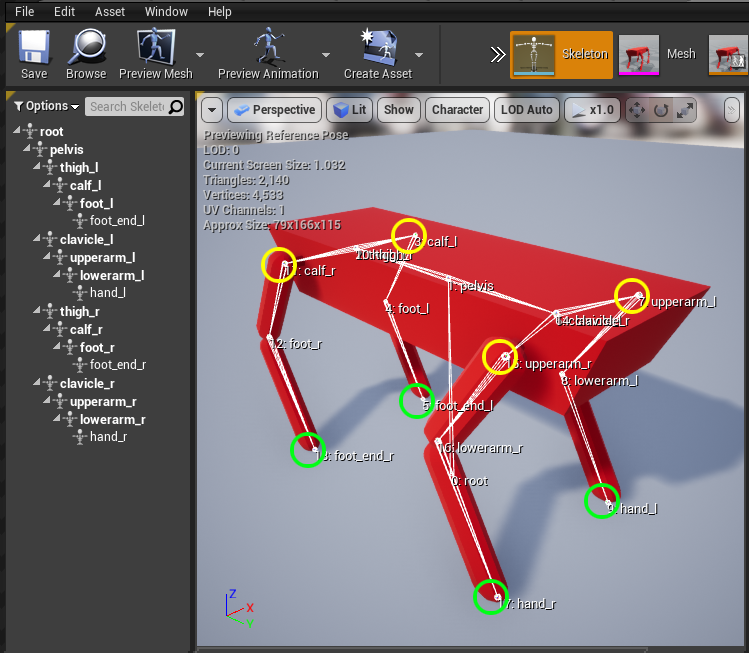
In this example, we see that the legs are:
upperarm_ltohand_lupperarm_rtohand_rcalf_ltofoot_end_lcalf_rtofoot_end_r
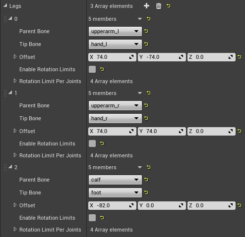
The beginning bone of the leg is referred to as the Parent Bone and the ending bone as the Tip Bone. Expand the previously created Leg entries and fill them in with this information:

Leg Groups
We can now set up the walk cycle by deciding which legs unplant together. The Leg Groups property allow you to specify exactly that.
Our Dog robot has a simple move cycle, where two opposing legs move at the same time:
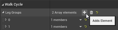
Therefore, we are going to create 2 new groups in our properties, by clicking twice on the + sign next to the Leg Groups property, inside the Walk Cycle section:
Remember that when we created our leg entries a Leg Index was assigned to each one of them? If we look at them again, we see that the following have been assigned:
- Leg Index
0isupperarm_ltohand_l - Leg Index
1isupperarm_rtohand_r - Leg Index
2iscalf_ltofoot_end_l - Leg Index
3iscalf_rtofoot_end_r
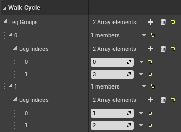
What we want is therefore to have the following groups:
- Group
0contains legs with indices0and3 - Group
1contains legs with indices1and2
Let set them up. The end result looks like this:
Leg Offsets
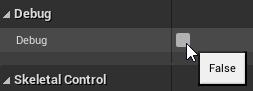
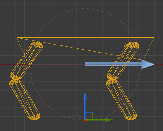
Enable Debug:
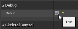
Then click Compile. This will display the ray traces in the preview window:
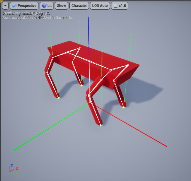
There are two things that we need to ensure at this stage.
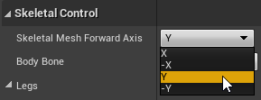
First, check the Skeletal Mesh Forward Axis. You see here that the X (red bar) drawn under the Dog correctly points to the dog Forward axis. If this wasn't the case, we can set the correct axis using the related property:
Second, every legs' Ray Traces should point to the position where the feet rest when idle.
To do that, we need to modify the Offset properties available on every leg, if necessary. These define every leg's Tip Bone offset from the Parent Bone. This is where the feet will rest when idle, and will be used to compute the steps.
In the Dog example we don't need to do anything because the Ray Traces already hit the legs. If they didn't, it would be necessary to set the Offset properties that can be defined for every leg.
For example, let's look at the Tripod example:
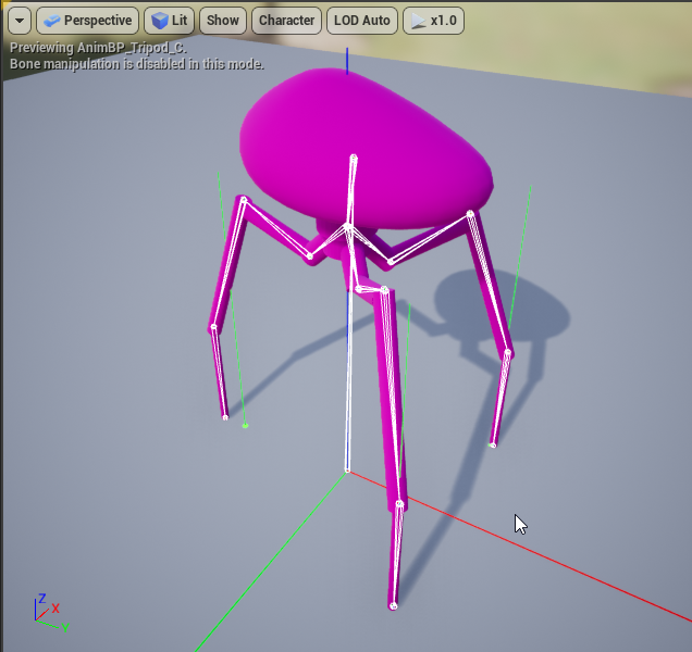
To achieve this result, we had to modify the offsets as follow:
Tip
You may notice that the Ray Trace for the leg behind does not exactly hit the foot, but is actually a little in front of it. This has been done to try to have the legs more equally distanced than what is provided by the model itself, so that the Walk Cycle appears more balanced.
You may now disable the debug:
Compile and Save.
Set up the Character
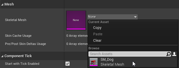
In your character, set your Skeletal Mesh:
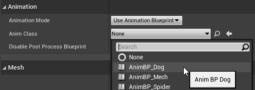
Then, set the Animation Blueprint that you have just created:
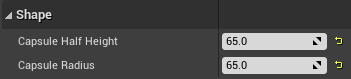
Now let's:
- Adjust the capsule size:
- Move the Skeletal Mesh to the appropriate position:
Repeat these last two steps as needed.
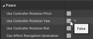
Finally, in the Character's Class Defaults, ensure that Use Controller Rotation Yaw is disabled:
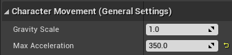
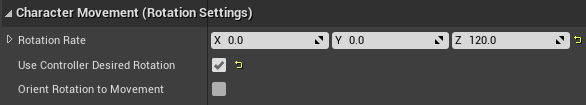
In the Character Movement Component, adjust the:
Max Walk Speed
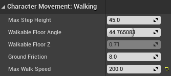
Max Acceleration
Rotation
Once done, start your game and you should see your character walk: