Node Configuration
Simple Procedural Walk
Debug
Turns debug on / off. When Debug is on, traces and other computations will be drawn around the character both in the Animation Blueprint preview window and in game. Also, some information will be printed out on the screen.
Scale With Skeletal Mesh
(advanced setting) Sets whether to scale values such as StepHeight, Step Distance Forward and StepDistanceRight relative to the scale of the Skeletal Mesh (true by default).
This allows to use the same actor with different scales, without the need of creating different animation blueprints. Turn it off if you want to set absolute values instead.
This has no effect if the Pawn / Character scale is the default (1, 1, 1).
Detect Falling
(advanced setting) Sets whether to detect if a Pawn / Character is falling. If set to true (the default), the Pawn / Character movement will adapt to falling
and call the interface events related to falling. Note that for a Pawn this requires an additional Box Trace.
Skeletal Control
Tip
Simple Procedural Walk only animates the leg chain and (optionally) the body. If you want to add some animation to other bones (such as tails, or other bones attached to legs) you need to use an IK Solver to define the intended behavior of your other bones. In UE4 you have some IK solutions (such as CCDIK or FABRIK) that provide solver nodes that help completing the setup.
Skeletal Mesh Forward Axis
Simple Procedural Walk needs to know which direction your mesh is facing at (aka the Forward Vector). Many Skeletal Meshes have their forward direction along the Y axis, i.e. the Unreal Mannequin.
To know which direction your mesh is pointing at, open it up in the Skeletal Mesh preview (by double-clicking on the asset) and look fo the coordinate system on the bottom-left of your preview window:
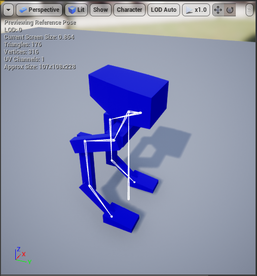
As you can see, the mesh is pointing towards the Y axis. Set the value of this axis in this property.
Body Bone
If you wish for Simple Procedural Walk to animate your body as well (rotation and location), specify the bone of the body that should be moved.
In most rigs this bone will be named pelvis or body.
Legs
This property defines the legs of your creature. Every leg that you want to be animated must have its own entry.
Index
The index of the entry (the number on the left, in the example 0) is called the Leg Index. This gets automatically assigned when you create an entry.
Parent Bone
This is the bone your leg starts from. See Getting started on how to select this bone.
Tip Bone
This is the bone your leg ends in, generally the hand or the foot. See Getting started on how to select this bone.
Offset
Simple Procedural Walk uses the Parent Bones locations to decide where to set the Tip Bones (feet) positions.
The Offset property allows you to set the necessary offsets to ensure that the feet get positioned correctly.
See Getting started for an example on how to set these offsets, or browse the Animation Blueprint of the various creatures provided in the downloadable example
Note
While the Z offset is provided, this should only be used for minor adjustments. For proper movement, your model should have Feet Bones, please check the Character & Mesh section for more information.
Enable Rotation Limits
With this property checked, your legs' bones' rotations will be constrained to the angles specified in the next property.
By default, no rotation limit is applied.
Rotation Limits per Joints
This array gets initialized for you automatically depending on the bones you select as Parent and Tip.
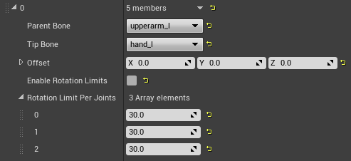
In the example, there are 3 bones involved in the leg with index 0:
upperarm_l(the Parent bone)lowerarm_lhand_l(the Tip bone)
Therefore, this array contains exactly 3 elements (the same number of the bones in the leg's chain).
These specify the symmetry rotation limits per joint, in degrees. The first element of this array matches with the Parent Bone, and the last matches with the Tip Bone.
In this case, the second rotation limit therefore refers to the rotation of the lowerarm_l bone.
By default, the rotation angle is set to 30 degrees for each bone.
Note
These contraints are the same ones as UE4 standard CCDIK, which means that they are symmetrical rotations angular limits. Therefore, the constraint direction cannot be specified, only the angle around the joint.
Walk Cycle
This section defines how your character walks.
Leg Groups
This is where you define how your legs are grouped together. Legs that are in the same group will unplant and plant at the same time, so they will basically have the same movement.
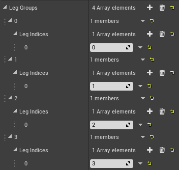
For example, a character with 4 legs could move two opposite legs at the same time (such as the Dog in the downloadable example), or it could move one at a time. The latter would probably best fit a big robot:
→ model not included in plugin ←
As anticipated, your legs have all assigned indices, all you need therefore to do is create groups and group the legs. For example, the model here above moves each leg separately so its configuration is as follows:
Min Distance To Unplant
(advanced setting) A leg will not unplant if it's not distant enough from the desired location. This property defines how much this distance should be.
Warning
Setting this value too high might have unexpected consequences on the walk cycle.
Fix Feet Targets After Percent
The feet targets are constantly computed during a step, until the step reaches a certain percentage. This setting defines it.
Feet Tip Bones Rotation Interp Speed
(advanced setting) Feet (tip bones) have their rotation set while on ground. This defines the interpolation speed.
Step Control
This section defines the walk steps.
Step Height
This is how high your step should be from the ground, when the step reaches its peak.
Step Distance Forward
This is how much far should the step aim at in front or backwards.
Step Distance Right
Since most models are longer than larger, we allow to set a separate step value when the model is moving sideways.
Step Sequence Percent
Defines at which percentage of a step the next group of legs will unplant.
- With a value of
1, a group will wait for the previous group to finish the step before unplanting. - Values between
0-1will make a group unplant while the previous group is still unplanted. - With a value of
0, all groups will unplant at the same time.
A video demonstrating a change in those settings can be seen here.
Walk Curve Type
Defines the step curves. Can be Robot (the default), Organic or Custom. If set to Custom, you will need to set the desired curves
in the Custom Step Height Curve and Custom Step Distance Curve properties in the advanced section below.
Step Slope Reduction Multiplier
(advanced setting) This defines how much the step distances (forward & sideways) get reduced when the Character is walking on a slope.
A value of 1 specifies no reduction. As example, a value of 0.7 means a reduction of 30%.
Min Step Duration
(advanced setting) The minimum step duration (steps should never take less than this amount of time). This is particularly useful when a character stabilizes, to avoid it having very quick steps increase this value.
Warning
Setting this value too high might have unexpected consequences on the walk cycle.
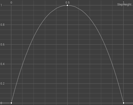
Custom Step Height Curve
(advanced setting) The custom curve that defines the foot height evolution during a step.
Time and Values need to be in range (0, 1).
Walk Curve Type needs to be set to Custom for this property to be editable and used in game.
As an example, this is what the Robot Step Height Curve looks like:
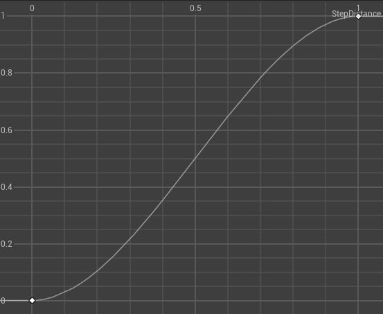
Custom Step Distance Curve
(advanced setting) The custom curve that defines the foot distance evolution during a step. This is how quickly the foot moves from the moment it unplants till the moment it plants.
Time and Values need to be in range (0, 1).
Walk Curve Type needs to be set to Custom for this property to be editable and used in game.
As an example, this is what the Robot Step Distance Curve looks like:
Body Location
This section defines how your body moves up and down.
Body Bounce Multiplier
This defines how much your body should bounce up & down due to the steps the legs are taking.
Higher values make the body bounce more, a value of 0 disables the bouncing.
This property needs to be set jointly with the Body Location Interp Speed, as the bouncing will depend on this value as well.
Body Slope Multiplier
How much should the body be lowered to the ground while on a slope.
Higher values make the body drop more, a value of 1 disables the movement.
Body Location Interp Speed
How fast should the body up & down movement be interpolated.
Body Z-Offset
(advanced setting) An optional vertical offset to be always applied to the Body.
Body Rotation
The body can be set to automatically rotate due to:
- The acceleration, so changes of speed in any direction.
- The feet locations, i.e. when on a slope the body can rotate to adjust to the slope inclination.
Body Rotate On Acceleration
Se to true if you want the body to rotate due to changes of speed.
Body Rotate On Feet Locations
Se to true if you want the body to rotate due to the feet positions (i.e. when on a slope).
Body Rotation Interp Speed
How fast should the body rotation movement be interpolated.
Body Acceleration Rotation Multiplier
(advanced setting) How much should the acceleration influence the body rotation.
Body Feet Locations Rotation Multiplier
(advanced setting) How much should the feet locations influence the body rotation.
MaxBodyRotation
(advanced setting) Allows to set the maximum rotation amoun, per axis.
Solver
Solver Type
You can choose between the BASIC or the ADVANCED solvers.
The ADVANCED solver (the default) is able to solve feet locations even on interrupted terrain (i.e. where there are holes, edges, or spikes).
Info
The ADVANCED solver will first try the BASIC solver's ray trace. Then, it will consider the distance between the hit point and the leg's Parent Bone.
If this distance is greater than a certain amount (configurable with the Distance Check Multiplier property)
then it will perform a Sphere trace (configurable with the Radius Check Multiplier property) to look for footholds.
Tip
The ADVANCED solver, though more precise, is also a little more costly than the BASIC one. You might want to consider using the latter for some performance improvements.
Feet In Air Inter Speed
(advanced setting) The interpolation of the feet locations when the Pawn / Character is in the air.
Radius Check Multiplier
(advanced setting) When using the ADVANCED solver, it controls the radius in which the legs should look for a foothold.
Distance Check Multiplier
(advanced setting) When using the ADVANCED solver, specifies when the basic vertical location where to plant the foot should be abandoned and a location within a radius should be searched for instead.
This is directly related to how much the leg can "extend" its Z axis when going from idle to walking.
IK Solver
This section covers the Inverse Kinematics solver.
Info
The Simple Procedural Walk IK solver is based on CCDIK (Cyclic Coordinate Descent Inverse Kinematics).
Enable IK Solver
Enables the IK Solver. If using Virtual Bones to drive your animations, you might need to disable the internal IK Solver.
Start From Tail
Start bone computations from tail.
Precision
(advanced setting) Specifies the tolerance for final tip bone location delta.
Max Iterations
(advanced setting) Maximum number of iterations allowed, to control performance.
Trace
Trace Channel
Allows to choose a Trace Channel.
Tip
It is recommended to have a Trace Channel dedicated to feet placement. This allows to have a fine-grained control so that, for instance, feet are not placed on top of grass or small foliage.
Trace Length
Specifies how much the ray trace should vertically go down from the Parent Bone.
Warning
This value should at the very least be the height of your Skeletal Mesh, but it's recommended to set it to a much higher value. A value set too low would compromise the computations of the desired feet locations, hence disable a proper walk cycle.
Trace Complex
Set to true to enable a complex trace (the default).
Trace Z-Offset
How high should the trace start from the Parent Bone.
Tip
If your model has a very low Center Of Mass, you may have your Parent Bones very close to the ground (think of spiders for example). In this case, the ray traces starting from the parent bones may be lower than the ground itself, and therefore provide invalid calculations.
If you experience this situation, increase this value, but first enable Debug and check that your ray traces come from high up enough to hit the ground.
Warning
Do not exceed in this value, as too high values might provide desired feet locations on higher grounds (such as floors above the Character).